Tube & Generator Loading Fixture (TGLF)
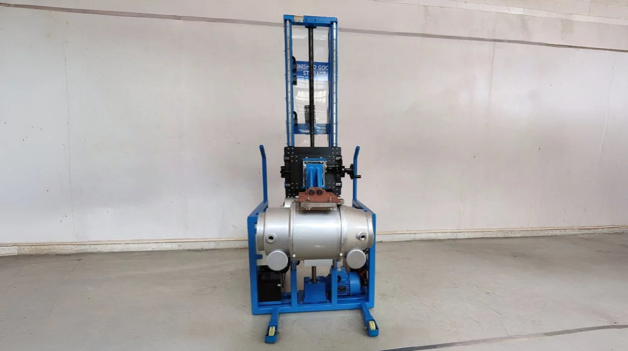
Tube Generator Loading Fixture (TGLF) was a fixture developed by Edify for a healthcare OEM, to help load the CT tube and Generator onto a respective gantry. This fixture helped reduced inaccuracy, and enabled effective utilization of manpower, as the OEM was previously utilizing up to three personnel for loading the components using Pulley/Chain/Rod mechanism. The TGLF enabled the hoisting by means of an electric motor that helped in accurate raising of the generator or tube to the requisite height. The fixture arms were also designed to move horizontally to ensure the components could fit in their slots appropriately. The fixture could adjust the angle during generator movement & vary the vertical height of tube loading using the worm gear. Though the horizontal movement was manual, it was more accurate than the then existing method of hoisting as the fixture helped in holding the component in a steady state, which avoided the swaying movement with minimal manual intervention. This gave the operator time to gauge the component's position and load it on to its position, in a hassle-free way.

PET-CT Table Transfer Trolley (PCTT)
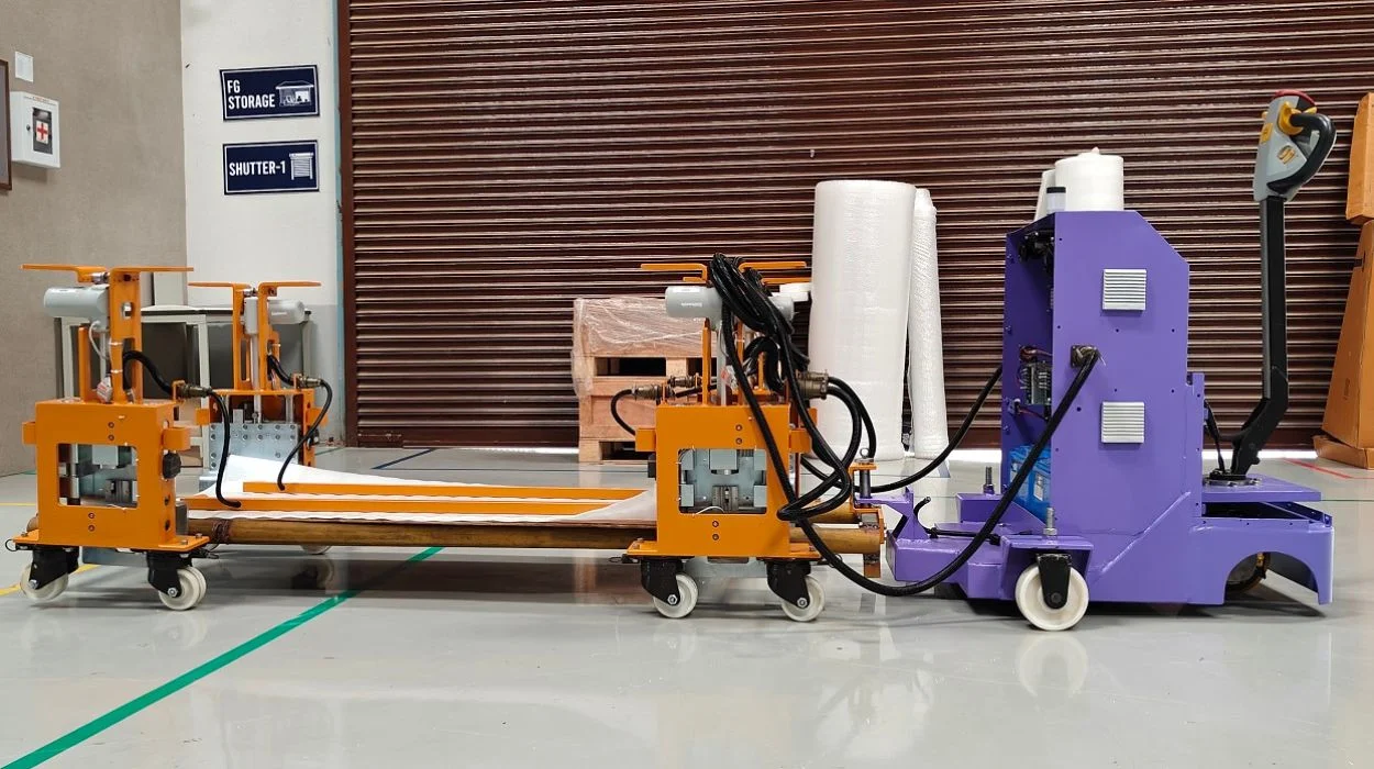
The PCTT was a transfer trolley developed for a healthcare OEM that had a basic fixture in place to lift the PET CT table and transport it from loading area to testing bay and from testing bay to packing facility. It was a manual fixture that worked on lead screw mechanism. The transportation of the table was done manually by using a castor wheel and a dolly. The PET CT table being quite heavy, weighs about 1T, and is loaded on to the test bay by lifting the four fixtures in each corner individually. This lead to non-uniform lifting of the table that further lead to errors in positioning, and cost both time and efforts. And this was where the PCTT pitched in, especially to semi-automate the process of lifting the PET CT table and ease the transportation of the table. The process of lifting was eased by means of linear actuators that ensured uniform movement of all four corners while either lifting or lowering. The movement of the PET CT Table was done using a transfer mechanism that was a part of the PCTT. Thus, both the movement of the table and the raising and lowering of the table was made easier to handle, reducing the human efforts required and saving time. This method proved to be ergo friendly in the loading and transferring of the PET-CT Table.

Wire Cut & Tinning Automation (WCTA)
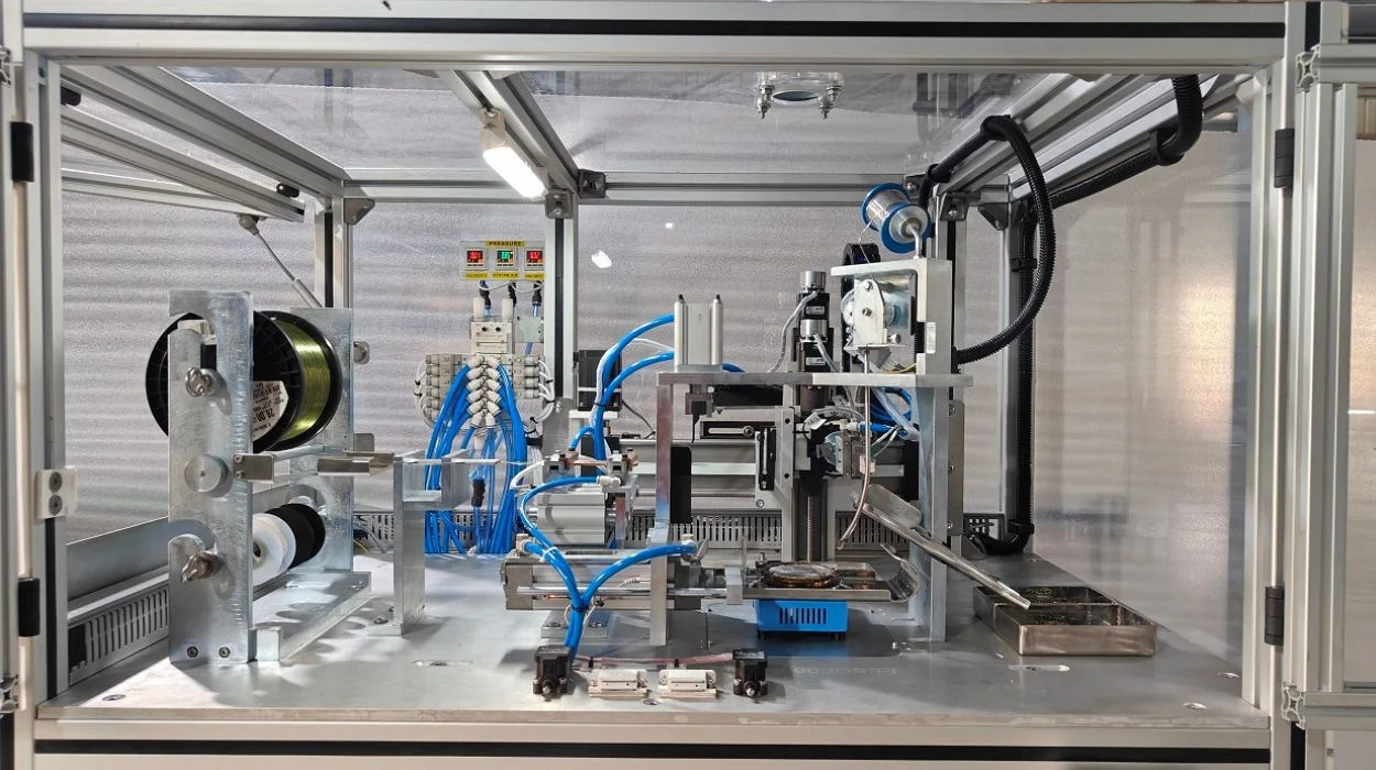
The WCTA was a step ahead in solving a production line issue, presented to us, by our customer. In the existing setup of wire tinning used by them, there were two magnetic wires being fed into an actuator, which dispersed them at a uniform rate to be cut at equal intervals. which were then held by two support brackets, and both the ends of the cut magnetic wires were dipped in a molten tin bath, one after the other. The tinned wires were then collected in a bin. In a requirement that needed us to change few of the internal mechanisms, we developed the WCTA station, which was developed to support the feeding of four magnetic wires simultaneously. Some of the key challenges we rectified when compared to the previously used tinning station was that the ceramic brackets holding the cut magnetic wires moved all the way down to the tin bath, as against the solder pot being raised to enable dipping of the magnetic wires. Along with this we also introduced a slide to safely move the magnetic wires to the wire collecting bins, which was one up over the previous arrangement of the wire collecting bin also moving towards the solder pot. This development also eliminated the use of an additional actuator, while keeping the wire collecting bins at a safe distance from the heat of the solder pot. A three-axis gantry replaced the pneumatic cylinders for enhanced performance and reliability. Lastly, an automatic slag remover and auto tin feeding features were introduced to remove slag from the tin bath and to feed the tin wires at specified intervals.

Mobile X Ray Handle Test Station
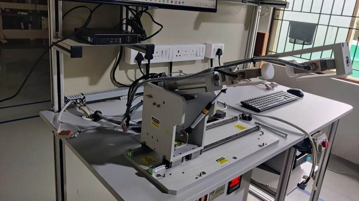
Any mobile X ray machine is a heavy structure. Being a mobile X ray machine, they are needed to have a simple manoeuvrability mechanism to move from one place to the other. This movement is controlled by its handle, including forward, reverse and steering movements. As per design, a sensing mechanism is incorporated in the handle assembly that provides an input to the system to engage the self-drive motor mechanism. Thus, the mobile X ray equipment shall be shifted from one place to another at ease, without much effort. This challenging project was handed to us by a healthcare OEM. As per the customer requirement, Edify developed a full-fledged test station, to confirm if the specifications of the sensing mechanism of the mobile X-ray machine's handle assembly were functioning properly. The architecture involved usage of servo motors, force measurement system, software, programmable logic control, and related electromechanical controls. This test station helped capture the handle movements' signals and verified if they were within the tolerances. Multiple tests were performed on the handle, and an exclusive program was developed to ensure that the PCB that was affixed in each handle was uniquely coded for traceability. The test station was provided with a report generation capability and captured the traceability, various tests, test data and results, which was put together in a document file.
